I’m almost finished putting together the latest addition to the AA0MS shack–an Ultimate 3S QRSS/WSPR transmitter from QRP-Labs and the mind of Hans Summers, G0UPL. I found my way to the U3S kit in a round-about manner: some time ago, after a few years of playing around with Arduino programming and projects, I purchased the ARRL book, Ham Radio for Arduino and PICAXE, in hope of finding some interesting radio projects that incorporated the Arduino. The first one that really captured my interest was a QRSS transmitter project, created by Hans Summers himself. The original project was an Arduino shield that Summers designed to be a a simple QRSS-mode transmitter (QRSS is a weak-signal mode involving very slow sending of CW signals for low-power propagation experimentation), and which eventually became the Multimode QRSS Arduino Shield kit (now retired). The original kit was available for three HF bands, and the Arduino software allowed selection of different QRSS speeds. The U3S kit is a much more full-featured multimode/multi-band transmitter that is capable of not just QRSS and WSPR, but also FSKCW, Hellschreiber, Opera, JT-9, JT65, and much more–more than 30 modes in all.
The article in the book mentioned above is meant to be used to assemble the QRP-Labs QRSS kit, but because the full schematic is provided, you can also build that transmitter from scratch, if you like. I built the circuit from the article for 30 meters, because I had a 10.140 MHz crystal on hand, and fortunately, I had all of the other parts handy as well. The Arduino code for the project was actually listed in the article in the book, but it was easy to find the download, and the programming of the Arduino was simple and error-free. I didn’t actually finish that project before I ordered and received the U3S kit, as my main interest was WSPR, and the book project was about QRSS–I don’t believe the Arduino sketch contained any code for the WSPR protocol. But the circuit did oscillate on frequency in my initial testing, and one of these days I will finish it up and try it on the air. Unsurprisingly, the low-pass filter for the book project is essentially identical to the low-pass filter kit I ordered with my U3S kit.
WSPR is the mode that attracted me to the U3S kit–the acronym stands for Weak Signal Propagation Reporter, from the mind of Joe Taylor, K1JT. The software behind WSPR (on the transmit side) configures CW transmissions that are very, very slow, requiring several minutes to send a call sign, and usually sending those transmissions at QRP power levels or lower. A WSPR transmitter essentially functions as a beacon, sending messages continually according to the WSPR protocol. The default power output setup for the U3S kit is 200 mW, with one BS-170 FET as the power amplifier, though the kit can be modified to use as many as three BS-170s, or to drive an external power amplifier. On the receive end, a WSPR receiver interfaces with a computer which looks at the incoming signal (on one of the agreed-upon WSPR frequencies) and decodes it, if possible, recording the reception in an Internet-accessible database which one can search for one’s callsign.
In other words, once I get this U3S transmitter on the air, I can leave it running for as long as I wish, and after a time, search for my callsign on the WSPRNet database (I have a mobile app called WSPR Watch that makes this pretty easy). Wherever my callsign appears, there will be information about the location of the receiving station, which helps me sort out what sort of propagation path my transmitter was able to use, and how far away my signal could be received.
The kit was shipped to me from Turkey–I hadn’t expected that, but had I looked at the QRP-Labs discussion group on Groups.io prior to ordering, I would have learned that. It took about two weeks, which didn’t bother me too much, having ordered numerous components and parts from China over the years. The box was a little beaten up, also not a surprise, but it was packed well, and no parts were damaged. A quick inventory of parts showed that everything was there, as expected, but it’s always good to check. My order contained the U3S kit itself (the basic kit, which includes the main board, the display, and one low-pass filter kit–I chose 30 meters), plus a 10-pack of extra BS-170 transistors, just in case I smoked the one that was included, and in case I decided to add additional PA transistors to the main board. There are several options available to the builder when purchasing this kit–you can opt, as I did, for a single LPF board, or you can buy a relay-switched, multi-filter kit that allows the radio to be used on several different frequencies. You can purchase a GPS unit for automatic time-setting, geolocation of the transmitter, etc., and you can also add a nice aluminum case kit. The base price for the minimal kit is about $35 as of this writing, and you can get a kit with all the options for about $140 (shipping extra).
One of the features of the U3S kit is the inclusion of an Si5351 frequency synthesizer kit that allows the transmitter to be built for any frequency desired, from 2200m to 222Mhz. The synth kit consists of a postage-stamp-sized PCB with a handful of parts, and it goes together very quickly. The actual Si5351 chip comes pre-soldered to the board, as it is a very small surface-mount part (all other parts in the kit are through-hole parts). There are pads on the synth board for SMA connectors that can be used to access all three of the synthesizer’s independent outputs, should the builder decide to put it to other uses as a signal generator, for example, under microprocessor control.
The U3S kit ships without any documentation, but all of the information you need is available for free download on the QRP-Labs website. This means that you can read the assembly manual, the configuration guide, and the instructions for the various add-ons before you buy, if you wish, which I really appreciate. You’ll need to read the assembly guide carefully before you begin putting the kit together, because there are some options that you’ll need to learn about in order to decide how you will use your rig once it’s assembled.
When I get a new kit to put together, I like to clean up my bench, get all my tools and supplies in order and then wait for just the right time to begin the project, so I can work without interruption for a while. That didn’t happen for this kit. In fact, my bench was still a mess from just having finished the main construction of the QRSS transmitter, but I couldn’t help myself–I was so eager to get this kit built that I dove right in. I began with the low-pass filter kit, which was the most labor-intensive part of the project, as there were three toroidal inductors to wind. As it turned out, I should have waited and tempered my enthusiasm–in my haste, I wound the toroids backwards, and didn’t discover my error until I had wound all three, and then looked at the board to see that the toroids’ leads were not in the right positions for the holes on the PCB. This meant that I had to un-wind all three of the coils and re-wind them in the proper way. In fairness, there was nothing in the documentation that mentioned this detail specifically, but had I studied the illustration of the PCB just a little longer, I might have been able to avoid this error. No harm was done, and the second winding was perfect.
The way the LPF is designed, you can build additional filters for different bands if you wish (they are sold separately, though one LPF of the frequency you choose is included in the kit price) and just swap them in and out as needed. The multi-band, relay-switched filter option is another approach to making it easier to switch bands under software control.
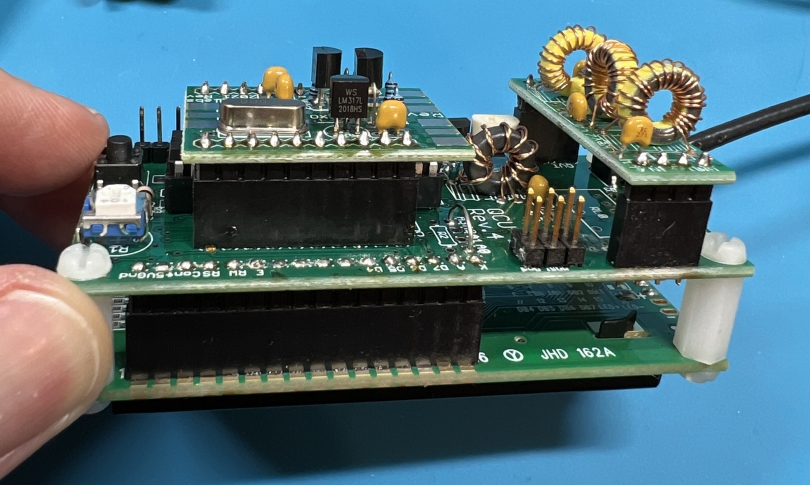
The next module I built was the synth module, which was a quick build. Both the LPF and the synth module are built with male header pins that allow the modules to be plugged into email headers on the main board. The main board construction took a little longer than the smaller add-on modules, and included one more toroid coil to wind, but the assembly process is not too difficult for any of the modules in this kit. One caveat, though: the PCBs are quite small, and most of the components are quite close together, which means that a very small soldering iron tip is needed. Fine-gauge solder is also helpful. The markings on the included capacitors are quite small, so a magnifying glass is helpful if your eyesight is anything like mine.
The kit requires a well-filtered, stable 5-volt DC power supply. The documentation notes that this is a very important requirement, and that some of the wall-wart switching supplies are unsuitable for powering the U3S. When wiring up the radio, there is an option to include a separate power supply for the power amplifier section of the circuit, so that it can operate at a higher voltage and thus, higher output power. Be sure to read the assembly documentation carefully concerning powering the unit.
When I was finished assembling everything, I plugged the four pieces (main board, synth board, LPF, display) together and connected the output jack to a home-brew QRP power meter with an integral dummy load, and then temporarily connected power. The LCD display lit up, but there was nothing on the screen initially, but a quick adjustment to the LCD contrast trimmer pot brought the word “Diagnostic” into view, which was an indication that the microprocessor was at least talking to the display properly. For the next several minutes I cycled through the menus using the two menu buttons while paging through the operation guide, which is a long and detailed document that covers every menu in the microprocessor software. I configured a few of the main options, such as my callsign and the default operating mode. When the transmitter was finally keyed, the power meter indicated that RF energy was being generated, and I could hear the signal on another receiver. And there was no smoke!

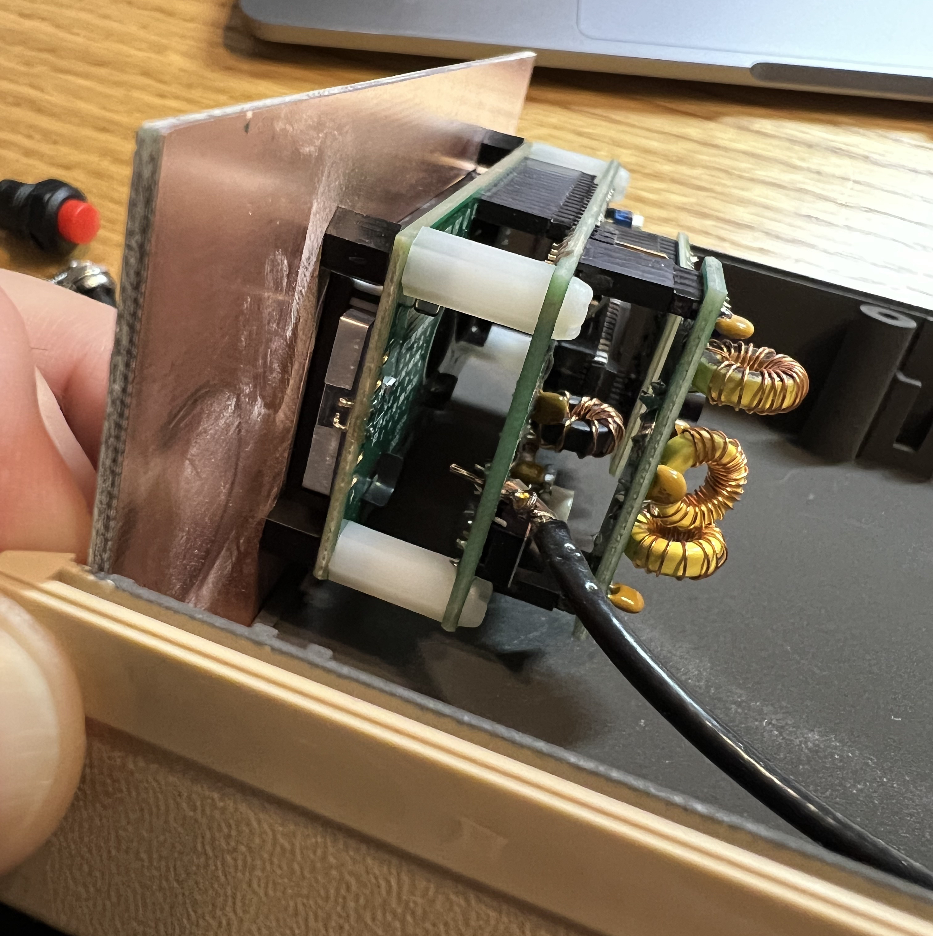
I decided to box the U3S in an old plastic project box–I have a bunch of these clamshell-style cases that are nickel-sprayed on the interior for shielding, but I don’t have any front or rear panels for them, so I cut double-side copper-clad fiberglass PCB material to the right size, and drill and punch as needed. The fit is loose, but hot-melt glue firms things up. Once I had all the holes in place, I spray-painted the panels, and when the paint is cured, I’ll do the final assembly. The only steps left after that are to finish the configuration for WSPR mode, and to calibrate the frequency synthesizer–also a software step.
My current antenna situation is fairly grim–just a piece of wire that extends from the window near my operating desk to a tree 35-40′ away. It’s adequate for listening for now, and I’ll try putting the U3S on that (through my tuner) and see what happens, but I have gathered all of the materials I need to build a dipole for up to 80 meters, and I hope to have that up and working soon. I will post a follow-up once I get some results.
Antenna matters have always been problematic for me. My first antenna was an indoor antenna, and not a particularly good one. I cut a dipole for 40 meters and installed it along the ceiling of an upstairs bedroom that was barely big enough for it. In fact, now that I think of it, it might have been a folded dipole made from 300-ohm TV twin-lead. My shack was in the basement, and I don’t recall how I ran the coax from my operating position to the upstairs room, but somehow it worked well enough for me to make a few contacts with my Drake TR-3 transceiver. Not many contacts, mind you, but I was never as excited about being on the air as I was about building gear and gathering test equipment and stocking my junk box.
I also didn’t care to run my rig anywhere close to its full power capability. Theoretically, the TR-3 was capable of 300 watts of transmitted power, but I rarely cranked it even as high as fifty watts. Most of the time I was happy to try to make contacts with five or ten watts (or less), and the one time I remember actually turning up the output to 100 watts, my straight key suddenly began biting me with RF energy that was making its way back into my basement shack. I had a lousy ground set-up, as I recall–there might have been a counterpose wire on the floor, or at best, a connection to a cold-water pipe.
But I digress. For this WSPR radio project, I hope to actually have a dipole in the air, higher than any antenna I’ve ever had before, and a ground rod in the ground with connection to my shack. The only problem is that we’re on the cusp of full-blown summer here in northeast Kansas, and every ham knows the best time for antenna work is either late fall, when the wind chills are brutal, or even the dead of winter.
Farewell until I have more to report.

